Broan HRV90H Service Manual Page 10
- Page / 28
- Table of contents
- TROUBLESHOOTING
- BOOKMARKS
- INSTALLER MANUAL 1
- VENTILATION SYSTEMS 1
- TABLE OF CONTENTS 2
- 1. S ERVICE 3
- ABOUT THIS MANUAL 3
- 1.2 PARTS ORDERING CHART 4
- Technical Support Department 4
- U.S.A.: 1-800-637-1453 4
- ZONE C SELECTION CHART 5
- 3. TECHNICAL DATA 6
- 3.4 DIMENSIONS 7
- 3.6 SPECIFICATIONS 7
- 4. TYPICAL INSTALLATION 8
- 5. INSTALLATION 9
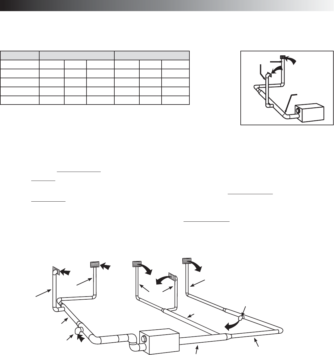
- 5.3 CALCULATING DUCT SIZE 10
- 5. INSTALLATION (CONT'D) 11
- 6. CONTROL DEVICES 15
- 6.2 OPTIONAL CONTROLS 16
- 6.3 OTHER FEATURES 16
- DECO-TOUCH 17
- DEHUMIDISTAT, DH100W, VT1W 17
- PLATINUM 17
- 60" (1.5 m) 18
- EHUMIDISTAT 19
- AND VT2W 19
- LATINUM / 19
- ECO-TOUCH DEHUMIDISTAT VT1W 19
- 8. WIRING DIAGRAMS 21
- 2001 HRV, ERV100HC, ERV200HC 21
- Models: HRV100H, HRV200H 22
- LOW COLLAR 23
- LOW MEASURING STATION 23
- 9.4 BALANCING PROCEDURE 24
- CONDENSATION CONTROL 25
- AIR SUPPLY CONTROL 25
- 10.2 OPTIONAL CONTROLS 26
- 12. TROUBLESHOOTING 27
- 13. REFERENCES 28
Related products and manuals for Air filters Broan HRV90H
 (22 pages)
(20 pages)
(12 pages)
(114 pages)
(22 pages)
(20 pages)
(12 pages)
(114 pages)
 (52 pages)
(10 pages)
(28 pages)
(52 pages)
(10 pages)
(28 pages)
© 2020, manymanuals.com. All rights reserved. | 2.997 s |
 Manymanuals.com
 Manymanuals.de
 Manymanuals.fr
 Manymanuals.it
 Manymanuals.pl
 Manymanuals.cz
 Manymanuals.es
 Manymanuals-pt.com
Comments to this Manuals